Deutsch
 Français

Monitoring System 500 For Server Cabinet Monitoring
The Monitoring System 500 is a proven solution for supervising critical rooms and technical environments, designed specifically for the continuous monitoring of IT infrastructures and sensitive operational areas. Its architecture combines advanced hardware with robust software, forming a dedicated monitoring appliance that can operate as a stand‑alone unit or integrate seamlessly into any SNMP‑compatible management platform. The system functions as a non‑stop monitoring solution for mission‑critical environments and is engineered without moving components to ensure maximum reliability. Instead, it uses a powerful ARM processor, a Linux‑based operating system and an intuitive multilingual web interface.
With eight sensor ports, the Monitoring System 500 allows precise supervision of essential environmental conditions such as temperature, humidity, airflow, gas levels, smoke development, water presence and potential water leaks. Each sensor can be configured individually, enabling tailored monitoring for the specific requirements of a server cabinet or technical room. For environments where network connectivity cannot be guaranteed at all times, the optional GSM modem provides an additional layer of security by sending SMS alerts directly to a mobile phone whenever a critical event occurs.
The Monitoring System 500 delivers dependable, real‑time insight into environmental conditions and ensures that risks are detected early, long before they can impact IT operations.
-
![]() Didactum Sensoreinheit Temperatur, Luftfeuchtigkeit und Rauch14035-Incl. 19% VAT , excl. Shipping Cost
Didactum Sensoreinheit Temperatur, Luftfeuchtigkeit und Rauch14035-Incl. 19% VAT , excl. Shipping Cost -
![]()
-
![]()

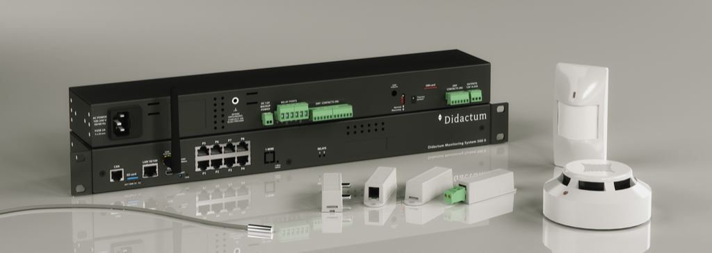
The Monitoring System 500 II is designed for the continuous supervision of important rooms and technical facilities. According to the document, it provides customers with a proven solution for protecting mission‑critical environments: “Mit dem neuen Monitoring System 500 II erhalten Kunden eine praxiserprobte Lösung zum Schutz unternehmenswichtiger Räume und Anlagen.”
This networked remote monitoring system can be used across industries. It is suitable for the permanent monitoring of IT infrastructures, including server rooms, data centers, production areas, logistics environments and technical facilities. The system is built as an all‑in‑one monitoring appliance, combining advanced hardware with intelligent software. A key advantage is that it operates stand‑alone, making it ideal for environments with mixed operating systems. The document states that it can also be integrated into SNMP‑compatible management software, ensuring that alerts continue even if a server‑based monitoring solution fails: “Sollte wider Erwarten der physische oder virtuelle Server… ausfallen, so werden Sie… zuverlässig benachrichtigt.”
As a non‑stop monitoring system for mission‑critical IT infrastructures, the device is engineered without moving parts such as fans or hard drives. It features a solid 19‑inch metal housing, an internal 230‑volt power supply and an integrated thermal sensor that protects the unit from overheating inside wall‑mounted or server cabinets.
The Monitoring System 500 II is used for temperature and humidity monitoring, remote supervision of unmanned technical rooms, monitoring of energy and telecommunications facilities, and rack monitoring of network and server cabinets. It is also suitable for data center infrastructure monitoring.
The system includes a powerful ARM CPU, a Linux‑based operating system, an integrated web server and a multilingual web interface. It supports essential protocols such as CAN, DHCP, HTTP, HTTPS, SNMPv1/v2c/v3, SMTP, FTP, RADIUS, SYSLOG, TLS and STARTTLS. Any change of state or critical event is immediately reported via email, FTP, Syslog or SNMP.
The Monitoring System 500 II is fully compatible with SNMPv1, SNMPv2c and encrypted SNMPv3 and can be integrated into leading network management platforms such as Nagios, check_MK, OpenNMS, PRTG, WhatsUp Gold and Zabbix. With the optional expansion board, the system also supports actuator functions, enabling automated control of external devices. If the optional GSM modem is installed, critical events can be sent via SMS, which is particularly useful during network outages.
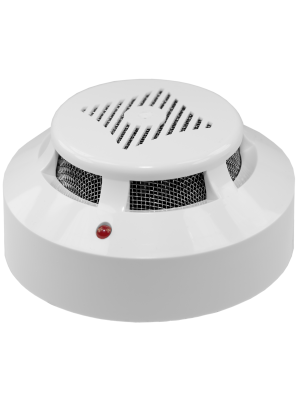
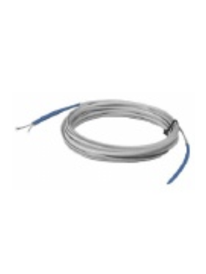
The system provides eight RJ‑11 ports for connecting environmental sensors. Users can select from a wide range of sensors to build a customized monitoring solution. The document lists available sensors such as temperature, humidity, airflow, gas, smoke, water and water leakage sensors, as well as security sensors including PIR motion detectors, microwave detectors, door contacts, glass‑break detectors, vibration sensors, light barriers, strobe lights and alarm sirens. It also supports current and voltage sensors for electrical monitoring. Each sensor is automatically identified and displayed in the web interface, and users can define custom thresholds, alarm values and notification types.
The Monitoring System 500 II includes an integrated IP data logger that stores real‑time measurement data. Storage capacity can be expanded with a USB stick. Sensor data can be analyzed directly in the web interface, exported as XML or CSV, and used for reports, audits or compliance documentation. The system can also transmit live measurement data via RSS feed.
An integrated alarm map allows users to visualize the monitored infrastructure, including sensor placement. Critical sensor values are highlighted visually, making it easy to identify issues at a glance.
The system includes a CAN‑bus port for connecting CAN sensors and CAN expansion units. Up to eight CAN units or CAN sensors can be connected, allowing a total of up to 64 sensors or digital contacts to be monitored in real time. The CAN bus can extend up to 305 meters, enabling monitoring of additional rooms and facilities.
An optional 1‑Wire module allows the connection of RFID card readers, electronic key readers or 1‑Wire temperature sensors. Up to 20 temperature sensors can be daisy‑chained over a distance of up to 100 meters.
With the optional expansion board, the system provides two additional relays, eight more digital inputs and a connection for 12‑volt backup power. External devices such as cabinet fans can be controlled manually, via SMS commands or through the system’s internal logic. For example, if a temperature sensor detects rising heat inside a rack, the system can automatically activate fans and deactivate them once the temperature returns to normal. Alerts can be sent via email, SMS or SNMP traps.
The optional GSM modem enables SMS alerts and remote SMS commands. Administrators can define allowed phone numbers and send commands such as switching relays on or off. Each command is confirmed via SMS. The GSM modem can also be accessed by external applications, and a free plugin is available for Nagios.
The system supports the integration of building technology into IT monitoring. It includes four inputs for digital contacts, allowing connection of UPS systems, HVAC equipment, emergency power systems, fire detection systems and sprinkler systems. Alerts can be sent via email, SMS or SNMP. If more digital contacts are needed, a dry‑contact unit with 32 or 64 inputs can be added.
The Monitoring System 500 II includes logic functions for notifications and alarms. Sensors can be grouped, and logical rules can be defined for automated actions. The document provides an example where rising server room temperature triggers fans at 30°C, activates additional cooling at 40°C and sends alerts to administrators while also forwarding SNMP traps to SCADA or network monitoring systems. All events are logged with date and time in the system’s syslog.
The system can also support USB video cameras, allowing images or videos of critical events—such as access to the server room or opening of a rack—to be sent via email or GSM modem.
The expansion board includes bi‑stable relays, additional digital inputs and a 12‑volt backup power connection. External devices such as 19‑inch cabinet fans can be controlled manually, via SNMP, via SMS or through the system’s internal logic. The document describes how the system automatically activates fans when a temperature sensor detects overheating and deactivates them once the temperature normalizes.